|
|
 |
 |
|
|
|
|
|
|
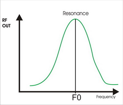
2. At the resonant frequency F0 the antenna generates the maximum voltage across the antenna and the maximum current through it, with the correct phase relationship. Efficiency drops rapidly as you move away from the resonant frequency 3. Will an ATU resonate the antenna? NO! 4. Will an ATU change the antenna SWR? NO! 5. Will an ATU ensure maximum output? NO! 6. So what does an ATU do in a mobile installation? It can fool the transmitter and the operator, but not the antenna! 7. Most amateurs have become used to tuning for a minimum indicated SWR. This is meaningless in a mobile installation. WHY? An efficient mobile whip is unlikely to be 50 ohms. An inefficient one may be! Minimum SWR is NOT an indication of maximum radiation; it simply means the tuning device has found a point where it thinks the antenna exhibits 50 ohms but, to achieve this the voltage and current will not have the correct phase relationship for optimum radiation. 8. The only sure way to tune an antenna is to change its physical characteristics. 9. Once the antenna has been resonated at the operating frequency, an ATU can then be used as an Impedance Transformer. 10. If the loading coil is placed at the top of the antenna, the RF current flows through the entire length of the antenna, giving rise to the highest radiation efficiency for a given antenna length. On the negative side, raising the inductor reduces the capacitance to ground, with the result that more turns are required on the coil to resonate the antenna. Unless heavier gauge wire is used, the DC resistance of the coil will increase raising the base impedance but reducing the overall efficiency. Top loaded antennae may be difficult to manage mechanically in a mobile installation and may be more suited to fixed base operation. An interesting characteristic can be observed by increasing the length of antenna below the loading coil on a LF mobile antenna. Raising the coil also results in a reduced capacitance to ground causing an increase in F0 rather than decreasing it as one might expect with a longer overall antenna length. In effect if you increase the length of the base mast, it will also be necessary to increase the top section capacitance to bring the antenna back to resonance. 11. If the loading coil is placed at the base of the antenna it is mechanically more stable, making design simpler, especially for multiband operation;. The inductance values required are lowest minimising any resistive losses however; the radiation efficiency is low because there is little or no length of antenna carrying RF current. Typical ATAS and Screwdriver types (Jack of all trades but master of none!). 12. The Centre (or slightly above centre) loaded whip provides a good compromise achieving an optimum L-C ratio, mechanical stability, and good radiation efficiency. This type of antenna is usually confined to single band operation; the Hustler remains one of the best commercially available. The Webster Bandspanner dating from the 1960s was a commercially made multiband antenna with remote adjustment of the inductance. 13. Helically wound antennae made from a continuously wound coil may offer greater mechanical stability compared to a centre loaded whip of the same length however: the radiation efficiency is comparable with a centre loaded whip of similar length. Helicals are typically monoband however, G-Whip offered a three band helical employing a slide switch, and a removable top section. The base impedance of this antenna was typically 17 ohms on 28 MHz resulting in an indicated SWR of around 3:1 at resonance. 14. Low resistance grounding at the antenna base is essential for optimising performance as well as minimising noise and RFI. In a short vertical antenna the Earth current = Antenna current. The location of the antenna should take into account the presence of a good earth consequently, bumper mounting may result in better performance than roof mounting where obtaining a good RF earth may prove difficult. Mag mounts which provide no grounding at all may give rise to earth currents circulating in the feed cable!
 |
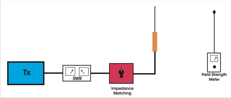
Do's ADJUSTING and MATCHING A MOBILE ANTENNA1. DETERMINE APPROX FREQUENCY OF ANTENNA by using:
2. APPLY SIGNAL SOURCE (Low PWR Tx)Sweep across required Band 3. Note "PEAK" on FS Meter (Distance >6ft) Maximum radiation. 4. ADJUST ANTENNA LENGTH to move "PEAK" to desired operating frequency. 5. CHECK MAX RF OUTPUT on desired frequency (FS meter). 6. CHECK SWR - Min SWR will not coincide with max field strength, may be as high as 3:1 at resonance
7. MATCH BASE IMPEDANCE to reduce SWR (ATU, AMU, Transformer etc) 8. Re-CHECK RESONANCE (FS Meter) 9. Make a Calibration Chart for adjusting the antenna length; it can be critical to 1/16th inch.
|

|
|
|
|
|
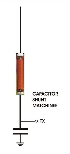
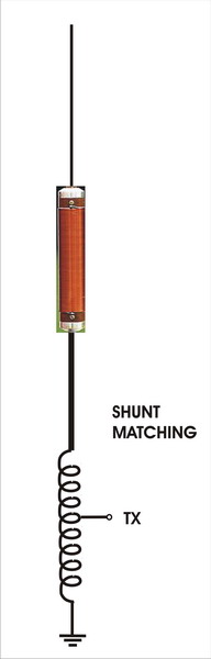
1. Capacitor series match allows some pulling of antenna frequency - single band operation 2. Capacitor shunt match OK for LF single band operation 3. Inductive shunt more suitable for higher frequency single band operation 4. Transformer match allows easy multiband operation for antennas between 12.5 and 50 ohms.. 5. Do not try to tune the antenna with the transformer! Change the length of the antenna. |

|
1. In Case A the hat is located just above the loading coil; this increases the capacitance to ground resulting in a lower value of inductance reducing resistive losses. The hat may take the form of an adjustable tuning element. Fairly common in the 1960s, but disappeared in later years. Little or no improvement in antenna performance. 2. In Case B the hat is placed at the top of the antenna; like top loading, it is designed to increase the current flow in the upper part of the antenna; top hats make the antenna unsuitable for mobile operation but can improve antenna performance. 3. Case C is a curious arrangement that has been observed in some CB antennas; whilst it might look impressive, adding capacitance below the inductor serves no useful purpose. |
|
|||||||||||||||||||||||||||||||||||||||||||
|
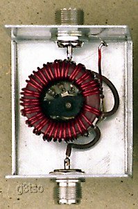
Transformer Matching Unit50 - 12.5 ohms
|
||||||||||||||||||||||||||||||||||||||||||
|---|---|---|---|---|---|---|---|---|---|---|---|---|---|---|---|---|---|---|---|---|---|---|---|---|---|---|---|---|---|---|---|---|---|---|---|---|---|---|---|---|---|---|---|